

Liquefied Natural Gas (LNG): Storage & Loading Operations – Manjur Khan (19N)
Introduction
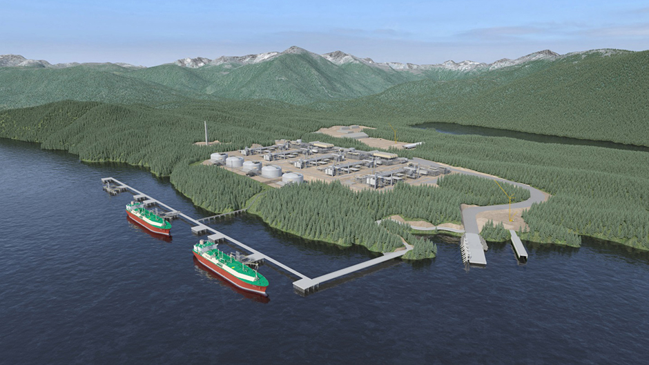
Liquefied Natural Gas (LNG) is a secure and eco-friendly energy source. It is produced in liquefaction plants close to the natural gas reserves and transported mainly by ship. LNG is exported and imported through LNG terminals, and delivered to local markets. The gas is distributed from the terminals to the customer in liquid or gaseous form.
Liquefied Natural Gas (LNG) is natural gas, predominantly methane (90%) with some mixture of ethane, propane, butane, some heavier alkaline and nitrogen that has been condensed into a cryogenic liquid through liquefaction process at close to atmospheric pressure by cooling it to approximately −162°C or less for ease of storage or transportation.
This article aims to explain, in simple terms, LNG storage, cargo loading operations at the loading terminal end. Throughout the article, references have been drawn from a wide range of resources and author’s personal industry experience. This paper is intended to share industry knowledge with wide varieties of audience including aspiring mariners.
The LNG Chain
The LNG chain starts with the gas production, usually from offshore wells, though some plants receive gas from onshore sources. The gas produced can be from a gas field (non-associated gas) or may be produced along with oil (associated gas). The distinction between associated and non-associated gas is important because associated gas must have LPG components (i.e. propane and butane) extracted to meet heating value specifications of the LNG product.
The produced gas enters the LNG liquefaction facility and goes through several steps of treating before being liquefied. The LNG leaving the liquefaction plant must be stored in suitably constructed shore tanks until a ship arrives to load and transport the product. For example, a facility making 8 MMTPA LNG, a 140,000m3 ship arrives every three days. The time it takes to load a ship once the loading pumps are started is about 12-15 hours.
LNG Terminal Storage
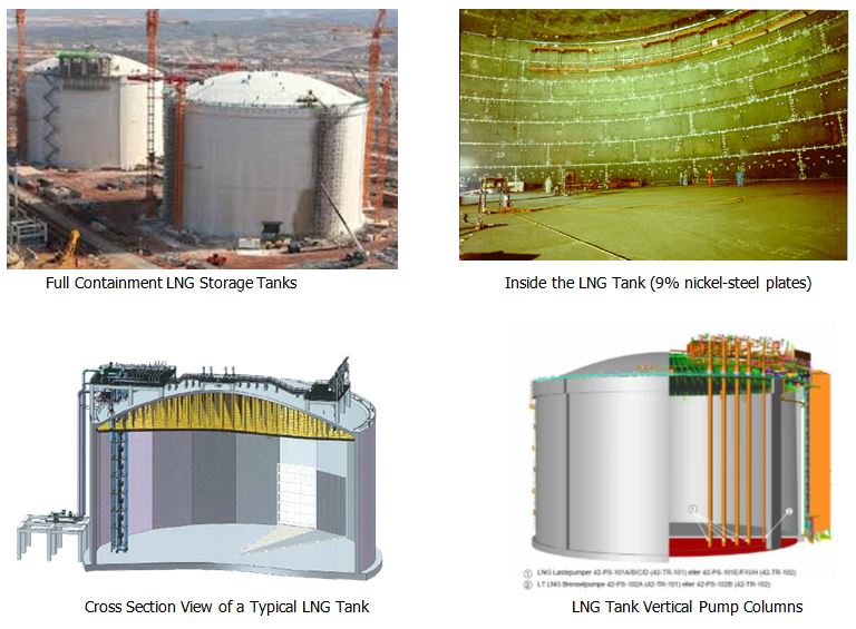
There are three common types of LNG storage tanks, known as “single containment”, “double containment” and “full containment”. In all cases there is secondary containment in the event of a spill, and the differences between the types is mostly in the method of secondary containment.
The ‘single containment’ storage has a 9% Nickel self-supporting inner tank and a carbon steel outer wall. There is perlite insulation between the two tanks. In the event of an inner tank leak, the outer wall fails because carbon steel is not capable of holding cryogenic materials. In this case secondary containment is provided by a dike surrounding the tank.
The ‘double containment’ tank has a post-tensioned concrete outer wall capable of holding cryogenic materials, and no dike is needed as the outer wall provides the secondary containment. However, the cold vapors contacting the roof may cause the roof to fail, thus the containment is not full containment because vapors may be released in the event of an inner tank leak. The ‘full containment tank’ is similar to double containment except that the roof is made of materials which can handle cryogenic temperatures and if the inner tank leaks all liquids and vapors are still contained within the outer wall and roof.
The LNG loading pumps are submersed into the LNG tank, inside pump columns, that extend to the tank roof, which houses the pumping elements. The key design feature of this pumping system is that it is possible to pull the pump for maintenance while continuing to operate the storage tank. A foot valve at the bottom of the column prevents LNG from entering the column when the pump is pulled. The operators purge the column with nitrogen and then remove the pump from the top of the column.
The LNG loading pump capacities are usually based on loading a ship in twelve hours. The liquefaction plant typically has multiple storage tanks and 2 to 4 pumps per tank. It is common to have a total of eight pumps running during loading, each with a capacity in the 1200-2000m³/hr range and 150-160 metres of head, and connected to loading lines leading to the terminal marine loading arms.
In many plants there is also a smaller pump in each tank in addition to the loading pumps. The purpose of this smaller pump is to recirculate LNG in the loading lines when no ship is present. The loading lines are large diameter (24-36”) may extend up to few kilometres, and must be kept cold between ship loadings due to cooling being a long and expansive process.
Transportation by Sea
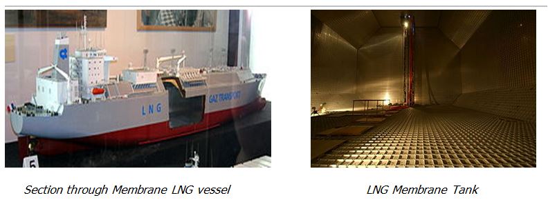
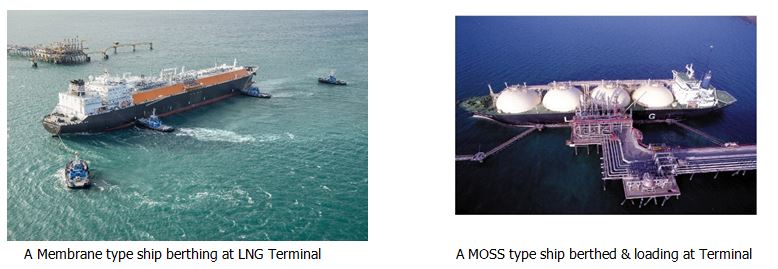
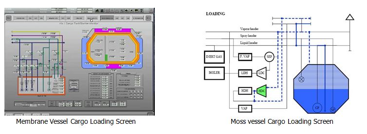
LNG is transported by sea on board specially designed LNG vessels. There are predominantly two types of tank construction system currently in use.
Membrane Types – LNG containment systems of the Membrane design generally fall into two categories that were originally designed by the two separate companies, GAZ Transport (GTT) and Technigaz. The membrane may be Invar (Gaz Transport) or stainless steel (Technigaz). The membranes in the NO.96 design are 0.7mm thick and each layer of insulation is about 200mm thick. The tanks are not self-supporting as in the Moss design; they are built against the inner (double) hull of the vessel. Nitrogen is purged through the insulation layers and a gas detection system is installed.
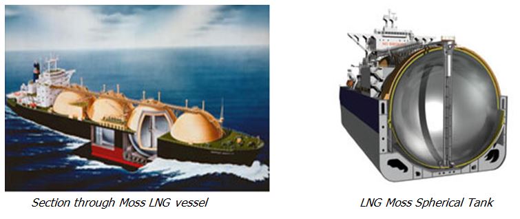
Moss Rosenberg Types – The Moss® LNG tank enables high accuracy of predicted stresses and fatigue life of all parts of the tank structure, eliminating the need for a full secondary barrier. The tanks are generally made from Aluminium and supported around the equatorial ring by a Structural Transition Joint (STJ), which also acts as a thermal break between steel and aluminium. The tanks are then insulated with polyurethane foam which is purged with Nitrogen. A partial barrier in the form of a drip-tray beneath the sphere is fitted. A gas sampling system is fitted to detect any signs of leakage. The complete tank and hold space are protected by weatherproof cover.
LNG Marine Terminal
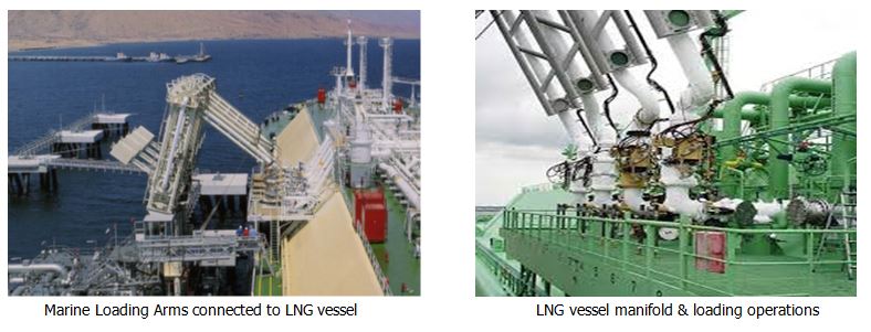
LNG terminal marine installations ensure the safe berthing and loading/unloading of ships transporting LNG via marine loading arms. LNG Terminals are usually constructed some distances away from the main LNG plant in a dredged pocket with sufficient depth for the LNG and Condensate vessels to moor and load. They are connected by a jetty from the landside which houses all LNG piping system. In most cases, terminals are well inshore from open seas, and connected by long dredged channel from the deep water contour line, marked with navigational aids. Vessels are piloted in and out of the port facility by licensed marine pilots throughout the life of the facility. These experienced marine pilots also act as LNG Loading Master, appointed by the terminal operator to manage ship-shore interfaces.
Marine Loading Arms
LNG being a cryogenic liquid, is usually loaded at any temperature below -159ºC. Normal steel loading arms or rubber flexible hoses cannot withstand such cryogenic temperatures. Thus, these are usually made of expensive special low temperature alloy which has a very good thermal expansion and contraction properties. One of the main reasons for using loading arms is their flexibility accommodating any movement, trim and list of the vessel during loading /discharging. These loading arms are always hydraulically operated and are fitted with emergency release couplings and emergency release system.
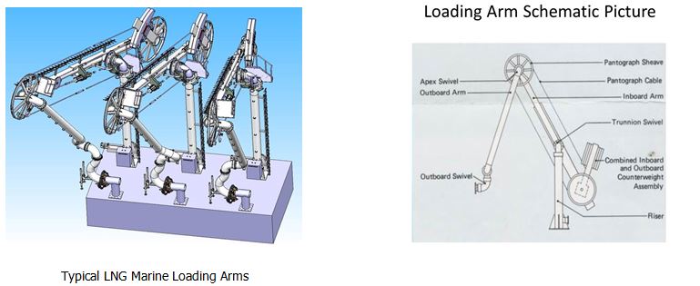
The loading arm has two swivel joints one at the top and the other at bottom. The top swivel and sheave connects both inboard and outboard arms. The bottom swivel and sheave forms the assembly for slewing and shore side dock piping.
The bottom sheave and swivel incorporates some counterweights to reduce the deadweight of the arm on the ship’s manifold connection, and to reduce the power required to manoeuvre the arm into position. The main idea of using a loading arm is to have sufficient ‘operating envelope’ for large ships. With Flexible hoses, the operating envelope is very less and it cannot accommodate large ships.
Loading Arms Connection
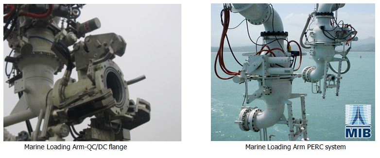
LNG terminals usually use QCDCs (Quick Connect/Disconnect Couplings). These are specially used for speedy connections. These couplings are hydraulically operated and manually controlled. The ship and shore flanges are locked mechanically (positive locking) independent of hydraulic power supply. The main advantage of the loading arm QCDC connection is the addition of the Emergency Release System, what is called as ESD-Emergency Shutdown. (Learn More¹)
In case of an emergency situation during loading/unloading operation, ESD can be activated from multiple points. In case of an ESD-1 activation, the terminal cargo pump is shut down and main shore loading valve is closed, protecting the ship’s loading systems. In case of a loading arm envelope breach, an ESD-2 is activated, which causes the PERC (Powered Emergency Release Coupling) of the loading arms to break away immediately in a safe way, disconnecting the arms to prevent further damage to shore infrastructures . (Learn More²)
LNG Vessel Operations
Considering that a LNG carrier is coming from the shipyard or dry-docking, the typical sequence of cargo operations would be as below:
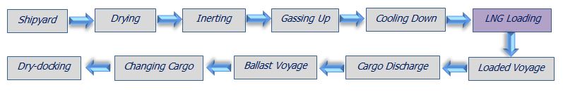
- Shipyard inspection – the first step is to thoroughly check that the cargo tanks are clean.
- Drying – any moisture must be removed from the tanks by introducing dry air from the shore or ship’s IG plant to avoid condensation and icing in loading system.
- Inerting – is necessary to ensure that tanks are not flammable. Inert gas from ship’s inert gas plant or Nitrogen (N₂) is used for inerting cargo tanks by displacement.
- Gassing up – inert gas from the cargo tanks must be displaced for CO₂ contents. Gassing‐up is done by piston purging LNG cargo vapour at appx +20ºC, displacing the inert gas /N₂.
- Cool‐down – is the process of slowly cooling cargo tanks to -110 to -130ºC by spraying LNG through the spray header lines. This prevents thermal shock to primary containment system. The ship tanks are readied to receive cargo and LNG loading from terminal may commence.
- A LNG vessel may need gassing up and cooldown at the loading terminal for extended time.
Terminal Loading Sequence
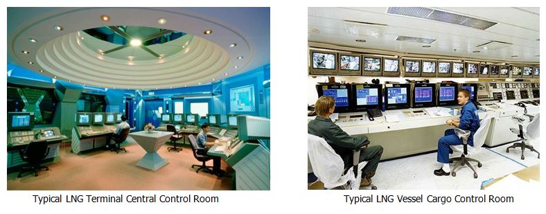
The safe, efficient and reliable loading of LNG into a vessel securely moored at the terminal is achieved by working as a high performing team involving many parties located on board and ashore. The Pilot Loading Master (PLM) is the primary terminal key representative co-ordinates with these teams. A PLM remains on board for the duration of the vessel’s port call. The LNG vessel’s Cargo Control Room and Terminal Central Control Room (CCR) are the main operational hubs during the vessel loading operations and port call.
High performing, modern LNG terminal loading operations would be in following sequences:
1. Pre-Loading Operations
- PLM confirms LNG vessel is secured at berth and main propulsion units are isolated.
- Terminal gangway put in position and essential personnel on board including PLM.
- Terminal ‘Ship-Shore Link’ (SSL) is connected. This is the primary link between the terminal and vessel CCRs, and the vital link for activating Emergency Shutdown (ESD).
- PLM chairs a pre-loading meeting with the Master, completes the ‘Ship-Shore Checklist’, which establishes the ground rules for LNG loading and vessel’s terminal call /stay.
- PLM then conducts an ‘ESD Logic Test’ from the vessel CCR, confirming a healthy communication link between the ship and shore CCRs.
- PLM conducts joint safety inspection on deck with the Officer of the Watch (OOW).
- PLM returns to vessel CCR and witness the initial cargo Custody Transfer Measurement System (CTMS) conducted by an independent Cargo Surveyor and Chief Officer.
- PLM oversees the Marine Loading Arms (MLAs) being connected by terminal technicians; ensures that MLA and vessel manifold flanges are in good order, and correct strainer is used, QC/DC is engaged and PERC systems armed.
- PLM then oversees the ‘Nitrogen Purging’ (>400kpa) and ‘Leak Testing’ process of the MLAs to terminal procedure and requirements ensuring O₂ contents below 1%. MLAs are bleed-off to a slightly positive pressure (50kpa) pending loading line cooling.
- Vessel hull protecting ‘Water Curtain’ is turned on and manifold trays to remain dry.
- PLM returns to vessel CCR and conducts a ‘Warm ESD-1 Test’ in preparation for MLAs cooling down. This test is initiated by the terminal CCR and ensures that shore ESD valve closes in <20sec, and ship’s manifold ESD valve closes in <30sec.
- After the satisfactory ESD-1 test, PLM asks for both ship and shore-side main vapour ESD valves to be opened for terminal to receive LNG vapour from ship’s vapour line. At least one of ship’s High Duty (HD) compressors is started to force vapours out.
- Once the vapour return is established, PLM asks for both the shore and ship main loading valves be opened, and all lined up to receive LNG for loading arms cooling.
- PLM asks Terminal to pump LNG at a controlled slow rate (5-15m³) to start cooling the loading arms and eventually increasing to appx 115m³, evenly cooling the MLAs and ship’s loading line. This cooling process may continue for about 60 minutes or so until ship’s tank header lines are cooled to ship’s satisfaction (-160ºC).
- Once the ship’s lines are cooled and ready for full cargo operation, PLM asks the terminal to briefly stop LNG flow, and initiate a ‘Cold-Stroke Test’ ensuring that the ship and shore ESD valves close, in their cold state, within the required time frame (15-30secs).
2. LNG Loading Operation
- Ramping Up – after the successful ‘Cold Stroke Test’, PLM in line with vessel loading plan, asks the terminal CCR to start loading and increase pumping rate to 1000m³, and closely monitors ship’s tank & manifold pressure, and cargo tank temperatures.
- Vessel crew to conduct checks on deck and manifolds ensuring that cargo is being received on board and no leakage or abnormality observed.
- Once satisfied with the cargo receiving, tank temperature and pressure, PLM asks the terminal CCR to increase pumping rate at 1000m³ increments up to the terminal full rate or max rate vessel can receive (9000-13000m³/hr).
- Full Rate Loading – Once the full cargo loading rate is achieved, vessel’s tank & manifold pressure and temperature are at steady state and within safe limits; PLM works out cargo completion time /ETD and advises all stakeholders. An emergency tug to remain standby on short notice.
- PLM and Master to ensure following are strictly adhered to during loading operations:
- No naked light and smoking in designated areas only
- Continuous deck, gangway and manifold watch by ship’s crew
- CCTV and visual monitoring of all manifold valves and overside discharge
- Mooring line tension and manifold line up with shore reference by monitoring MEMS (mooring and environment monitoring system) from PLM laptop /or CCR.
- Maintain intact stability, bending moment and shearing forces are managed.
- Continuous monitoring of weather, tide, current, squalls and UKC to survive/ remain at berth or depart in case of an emergency.
- Continuous monitoring of tank pressure, temperature and vapour discharge
- Ramping Down – LNG vessel tanks are generally loaded up to 98.5% capacity (99.5% with exemptions). At least sixty minutes prior to cargo completion, PLM with Chief Officer takes up position in the vessel CCR to gradually ramp down cargo loading. Ramping down at 1000m³ rates, with 5 mins to stop by calling the terminal CCR directly.
- Vessel tanks are planned for loading in a staggered sequence. PLM remains in direct communication with the Terminal CCR and calls to reduce rate as the tanks are topped up, and as requested by the vessel. ‘STOP Cargo’ is called by PLM to stop shore pumps.
- Stop Loading – after STOP loading call, PLM asks both terminal and vessel main LNG loading valves to shut, vapour return line and valves remain open for free vapour flow.
Draining & Purging of MLAs – once the ship and shore main loading ESD valves are closed, the terminal advises PLM their readiness to drain the loading arms ashore. Ship’s ESD valves are ‘inhibited’ at this point. Draining and nitrogen purging (>400kpa) process of shore-side arms, the MLAs and ship’s lines are done in accordance with the terminal procedures, to achieve hydrocarbon level <40% LEL or 2% by volume to disconnect MLAs.
Loading Operations Completed – completion of LNG loading operations is generally defined as the MLAs are drained to ‘liquid free’ and purged with N₂ and ready for disconnection.
3. Post-Loading Operations
- LNG Tank Gauging – once the MLAs are purged and ready to disconnect, PLM witnesses the final cargo custody transfer survey (CTS) conducted by an independent cargo surveyor and vessel Chief Officer. PLM receives a copy of the final load print out for Bill of Lading purpose.
- Loading Arms Disconnection – once the CTS is done, PLM asks the terminal technicians to disconnect the MLAs, vapour line being the last. MLAs are moved away and stored ashore. Vessel receives a cargo sample bottle, and commences on board preparations for sailing.
- Post-Loading Meeting – whilst the ship and shore are preparing for vessel’s sailing, PLM chairs a post-loading meeting on board with all ship-shore stakeholders. All required cargo documentations are signed off by PLM and vessel master, including any Note of Protest, and Terminal and Vessel Feedback Forms. Outbound Pilot boards the vessel.
- Vessel Departure – Once the post-loading meeting is over and required documentations are collected, SSL is disconnected, personnel ashore and gangway removed. Pilot orders tugs to make fast, and un-mooring operations commences. Vessel sails out without further delay.
Conclusion
Stringent operational and safety regulations govern the transport and storage of LNG. The LNG industry has an excellent safety record. The industry has technically and operationally evolved to ensure safe and secure operations. Technical and operational advances include everything from the engineering that underlies LNG facilities to operational procedures to technical competency of personnel. The physical and chemical properties of LNG are such that risks and hazards are well understood and incorporated into technology and operations on board and ashore. Modern terminals incorporate numerous safeguards in the design, construction and operation of the facility and employ state of the art technology. LNG is the fuel for future and the largest LNG ship owners account for half the global fleet(Learn More³).
List of References:
¹ https://www.youtube.com/watch?v=CWOJpnUavEM
² https://www.youtube.com/watch?v=DUaed0-uMyg
³ https://www.youtube.com/watch?v=rjlRTFyennU
http://www.giignl.org/
http://www.pianc.org/
http://www.sigtto.org/
http://www.lngworldshipping.com/index.htm
https://www.pumpindustry.com.au/pump-services-in-the-lng-industry
http://www.onthemosway.eu/wp-content/uploads/2015/06/LNG.-Cargo-operations.pdf
http://www.beg.utexas.edu/energyecon/LNG_Safety_and_Security_Update_2012.pdf
http://www.marineinsight.com/tech/construction-and-operation-of-loading-arms-used-for-lng-carriers/

[Authored by Manjur Khan (LinkedIn) – a master mariner (AMSA) with 25yrs experience in Australian maritime industry, currently serving as Marine Pilot Loading Master for Chevron Australia at Gorgon & Wheatstone LNG Project Terminals. Previously, within port regulation and operations, offshore oil & gas fleet operations, Commonwealth (AMSA) and State (NSW) maritime regulatory administrations, liner shipping cargo operations, and in maritime training institutes]


 has passed away….")
")


Recent Comments