


WYSIWYG – What You See Is What You Get – or is it?
The world of computing is strewn with acronyms, and so it might be considered appropriate to use one – WYSIWYG – What You See Is What You Get – as the basis for a critical analysis of Electronic Charts and the systems that display them. Electronic Chart Display and Information System (ECDIS) provides mariners with the facility to fully manage the display to show navigational objects and layers to the best advantage for the navigational conditions applying at the time. However, the appearance and content of the chart data displayed on ECDIS may change significantly from different settings as the display is generated as per the specifications characterised by the IHO (International Hydrographic Office) Presentation Library (S-52). Hence, navigators must recognise the level of display and the objects to display for the optimum navigational information for any situation.
Display Settings
Chart objects and information available for display are divided into three categories: Base, Standard and ‘All other’ display. The ‘Base display’ is an absolute minimum set of information which is permanently shown on the ECDIS display and cannot be removed from the screen. Its use may be helpful for initial appraisal in the planning stage as well as when moving the chart display to allow a faster re-generation of the display. However, it is not intended for safe navigation.
The ‘Standard display’, as defined in the ECDIS Performance Standards, includes the information contained in the Base display and most of the detail needed for safe navigation. It does not necessarily display all the chart objects required for safe navigation under all circumstances, e.g. underwater obstructions are not shown on the standard display, which is useful to know if it is intended to anchor. The ‘Standard display’ and other objects are all listed or classified as ‘All Other Information’ display and it is to be displayed individually on demand. Different manufacturers provide different facilities for managing the display of chart objects and chart information. Control of individual groups of objects, e.g. spot soundings, tidal diamonds, place names may vary according to each ECDIS manufacturer. Selection of certain layers of information or objects for display becomes more obvious with experience and mariners need to remember ‘Displaying everything, without seamanlike consideration, should not be an option’.
Navigators should take particular care when using the scale, or zoom facility. It is possible to zoom-in and select a larger scale than that used in the compilation of the data. Chart data is compiled at a specific scale and it is based on the hydrographic data from which the chart was created. This could create a false impression about the reliability of the charted data. For example, it could give the impression that safe water exists when it has not been possible to show all the dangers due to the limitations imposed by the scale of the original chart.
In the event that the displayed chart is not displayed at the compilation scale, and is not compatible with the selected usage (e.g. coastal or approach), then an overscale or underscale warning is displayed. Moreover, when the data displayed is from data of two different ‘Navigational Purposes’, the chart display will, where drawn at the larger SCALE, include an overscale area of data from the smaller scale cell in order to complete the Display. This area should be identified by the ‘overscale pattern’ of the IHO presentation library. (IHO Glossary, 2005). This overscale pattern (Prison bars) is generally displayed if the scale ratio of the display is more than twice the compilation scale of any charts in the display.
Another important feature that could lead to human/operator error where the users need to be very careful is known as Scamin (Scale Minimum). Scamin is an optional attribute created by the producer, (defined by IHO S57), which can be used to enable ENC chart features to be suppressed above a certain display scale. The main function of Scamin is to de-clutter the chart display, enabling the User to focus on the most useful navigational information for the display scale in use. Scamin may affect the display as it removes certain information from the display if the best scale chart is not being used. This feature should provide Scamin Filter warning to the users.
With some systems, it is possible to run a complete safety check for any hazards along the planned route at any time during the route planning process and on completion of planning. However, this functionality varies among the different makes. Mariners using ECDIS are reminded not to rely solely on automated voyage planning and monitoring checks and alarms. Some ECDIS appear only to undertake route check functions on larger scale ENCs and therefore alarms might not activate. This may not be clearly indicated on the ECDIS display. Mariners should always undertake careful visual inspection of the entire planned route using the ‘other/all’ display mode to confirm that it, and any deviations from it, is clear of dangers. (NAVAREA 1 Warning 317/10)
Safety Settings:
Navigators must understand the values for the safety settings on ECDIS and set them appropriately to achieve a sensible and well thought-out display. The safety settings required depend on the vessel’s location, movement and intentions. Failings in appropriate settings have recently resulted in a few grounding incidents; e.g. LT Cortesia and CSL Thames.
The safety contour marks the division between ‘safe’ and ‘unsafe’ water and it is highlighted by chart colouring, with blue colour to indicate unsafe area and white or grey for safe area. When the safety contour is not displayed to the specified value set by the navigator, then the safety contour is shown to the next deeper contour as per the default layers in the electronic charts. ‘Safety Depth’ feature affects the display of sounding colours as soundings same or shallower appear in black (soundings in bold format) and soundings deeper appear in grey. The unsafe area can be defined by the users with the selection of a shallow contour, showing dark blue in the shallow water and light blue between the shallow water and the safety contour. Additionally, the safe water may also be sub-divided with the selection of a deep contour, in which case the area between the

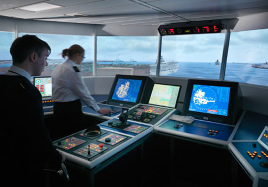
Figure 1: Appropriate safety settings are of paramount importance for ECDIS display
safe contour and the deep contour will be coloured grey. The shallow contour is considered to highlight the gradient of the seabed adjacent to the safety contour and the deep contour to highlight the depth of water in which own ship may experience squat. It is known that not all ECDIS manufacturers provide separate controls for safety contour and safety depth value, some have a common or a linked control. Some flexibility of the system is lost when there is only one common control for ‘Safety Depth’ for both the ‘Safety Depth’ and the ‘Safety Contour. The author recommends that the safety contour value should be used for the safety depth on ECDIS with such feature, if it is practicable.

Figure 2: The depth contours may differ between electronic charts produced by different hydrographic offices
Additionally, navigators must understand that depth contours can differ between electronic charts produced by different hydrographic offices. As an example in Figure 2, the depth contours of 5.4m, 10.9m and 18.2 m can be found on some U.S. ENCs (Electronic Navigational Charts), where the charted depths have been converted to metres from either fathoms or feet charts.

Figure 3: The need of appropriate value of Safety Contour to display a dredged area on an ENC
Another issue for a navigator to consider – what will happen if the Safety Contour value is set up less than the depth of any Dredged area? On the left-hand side display of Figure 3, the Safety Contour has been set up to 10m. In this case, Portsmouth entrance channel is not displayed as it has been dredged to 9.5m (middle display using ‘Pick Report’). However, if the safety contour value is set to 9m or less, then only the entrance channel is revealed (right-hand side display).
Accuracy and Reliability of ENCs:
The IMO Performance Standards for ECDIS require that the chart information to be used should be the latest edition of information originated by a government authorised hydrographic office, and must conform to the standards laid down by the IHO. Only officially approved vector charts must be used with ECDIS if it is to comply with the performance standards. A vector chart complying with IHO standards can display information that will enable the user to assess the quality of the hydrographic data used to compile it. Navigators should interrogate the quality while performing passage planning. By default ENCs are referenced to WGS 84, thereby ensuring compatibility with the electronic position fixing systems.
Mariners are advised that positions showed from Global navigation Satellite Systems, such as GPS, may be more accurate than the charted information, due to the age and quality of some of the source data. The CATZOC (Category of Zone of Confidence) in an Electronic Navigation Chart gives an estimate of the reliability of the source information. The hi-tech appearance of an electronic vector chart interfaced with systems such as GPS could mislead the user into the belief that the charted data is more accurate than is really the case. It will be a number of years before a significant number of vector charts exist with the accuracy provided by DGPS. For example, a stand-alone electronic navigation system, such as a GNSS will typically output its position to three decimal places (i.e. thousandths of a minute of Lat./Long.). The experienced navigator should appreciate that this does not mean that the position is necessarily accurate to 3 decimal places. When plotting the position on a paper chart he/she makes an informed judgement as to the confidence he may attach to that position. The problems associated with navigational error assessment should not change if an electronic chart is used instead of a paper chart. The navigator still has to verify 3 important questions:
• How accurate is the chart?
• How accurate is the navigation system?
• Is the navigation system compatible with the chart?
The accuracy of information on paper charts depends on two main criteria: the accuracy of the source data and the accuracy with which that data is projected onto the paper chart. In the past two decades the hydrographical survey process has been transformed by the introduction of satellite enhanced surveying systems which, when used in conjunction with side-scan sonar, or multi-beam (swath) echo sounders, enable surveys to be conducted more rapidly and more accurately than ever before. Nevertheless, it will be a number of years before the world will have been re-surveyed to a standard which is compatible with the accuracy available from satellite-based position fixing systems such as GPS. In some coastal areas (e.g. Indonesian coasts), it should be noted that a significant percentage of nautical charts is based on surveys which date from the late nineteenth and early twentieth centuries. These were carried out using traditional terrestrial based surveying methods. This should be of concern to the navigator and the UKHO continues to publish the following advice on paper charts:
“The Source Diagram or notes should be studied carefully before using the chart in order to assess the reliability of the data used”. Warnings are also published in the Mariners Handbook (NP 100) concerning the age and reliability of source data and the need to examine the source data diagram and the chart carefully. An example of MAIB Report No 18/2007 is given below:
The jack-up barge Octopus was being towed from Kirkwall to Seal Skerry Bay in the Orkney Islands by the tug Harald, to act as a platform for the installation of a prototype tidal turbine. The tug and tow altered their route to pass to the west of Little Green Holm Island, due to the strong tidal streams experienced during the passage, a route not usually used by deep draught vessels. As the tug and tow rounded the south of Little Green Holm Island the barge, which was being towed with its legs extended to a depth of 13m, grounded on an uncharted bank of 7.1m.
The applicable Admiralty chart for the area indicated a depth of greater than 20m with the closest sounding indicating a depth of 26m. The source data diagram on the chart indicated that the area was last surveyed, by leadline, in the 1840s.
Whilst most paper charts contain source data diagrams, ENCs (Electronic Navigation Charts) do not provide this information in the same way. Instead they provide the navigator with a facility to examine reliability and quality of source data by means of CATZOCs. The accuracy of ENC is generally the same information as the paper chart and they don’t have any greater accuracy and most ENCs have been produced by manually vectorising raster charts (scanned copies of paper charts). CATZOC gives an estimate of the reliability of data related to five quality categories for assessed data (CATZOC A1, A2, B, C and D) and a sixth category for data which has not yet been assessed. It is recommended to consider these CATZOC features while determining a ship’s safety settings as discussed earlier.
It has been recently observed that a lot of secondary lighthouses worldwide have been de-commissioned along with some primary ones and the removal of floating aids to navigation, purely based on the introduction of ECDIS, is a serious concern to mariners. Moreover, the existence of some virtual AtNs (Aids to Navigation) on ENCs by some hydrographic offices – e.g. virtual AIS buoys in Ushant TSS by the French Hydrographic Office (SHOM) – is a confusing feature, with navigators physically unable to identify them at sea. Another feature in ENCs are time varying objects. These objects will only show within the time frame embedded with the attributes. For example, the area on the Solent, east of the Isle of Wight – Navigators can see some of the special marks which are only visible during the month of March to October.

Figure 4: Less topographical (land) information may be observed on ENCs compare to the paper charts
It has been sometimes noticed that less topographical i.e. land information on ENCs, compare to the paper charts provided by some of the hydrographic offices. This is a great concern to the mariners. Here in Figure 4, the paper chart BA 2037 shows the ‘Horse Sand Fort’. This land feature is very important for the mariners to cross-check own vessel’s position and it can be easily read and identify from the paper chart. Unfortunately, on the ENC, it is only found under the ‘Fortified structure’ as an object name. Sometimes, it is very difficult to find out the information from an ENC using the ‘Pick Report’ facility.
Monitoring – Integrity check:

Figure 5: Radar Overlays to check the integrity of System. A) No Error, B) GPS Error, C) Gyro Error
When monitoring a route, the prudent navigator must always maintain a check on the integrity of the displayed position of own ship. When the source of the displayed position is the own ships GNSS, there is always a possibility that the position displayed may not coincide with the ship’s actual position in relation to the chart or the charted hazards. A check may be made quite simply by utilising one or any of the following:
• look out of the window;
• manual position fixing (visual/Radar);
• comparison of ARPA overlay of a fixed mark with the charted position;
• comparison of a radar overlay with conspicuous land or fixed targets;
• observation of a parallel index on the radar display to monitor comparison with planned track;
• monitoring the depth shown by echo sounder where appropriate;
• checking the track history;
An approved ECDIS system reduces the navigational workload compared to using the paper chart and it enables navigators to execute in a convenient and timely manner all route planning, route monitoring and position plotting as performed on paper charts. We must remember ECDIS is not different from the paper charts. Experienced mariners should use ECDIS with their existing traditional skills and paper chart techniques along with their previous experiences in the passage plan. Navigators must recognise the limitations on ECDIS display as well as the need for effective ECDIS display management, considering the most appropriate acronym ‘WYSIWYG – What You See Is What You Get’- as the basis for a critical analysis of ECDIS display.
![]() PDF Version [Published at SMC Magazine “নোঙর” May 2014]
PDF Version [Published at SMC Magazine “নোঙর” May 2014]
———————————–

[Zakirul Bhuiyan MSc, PGCE, FNI, AFRIN has been working as Senior Lecturer for Warsash Maritime Academy since 2006. He was invited as an invited speaker in numerous national and international maritime navigational conferences. He has also carried out researches on ECDIS and ‘Simulation Training’ with the outcomes published in a number of international publications. He hails from 23rd Batch of Bangladesh Marine Academy.]


Dear Sir,Good evening.Greetings from my organization(Reputed Govt. Org).I should say i become your fan by reading your article on ECDIS.Sir, my organization is looking for an ECDIS expertise to conduct a basic training on ECDIS operation at Chattogram.Can you help us by attending as guest Instructor? Nation will be highly benefited.
Best Regards
SHAHID